Introduction.
This chapter is useful for customers who wish to write their own computer program to interface the instrument to a computer.
This chapter includes description of Hardware and Software specifications required for the interfacing.
There is already written communications software
program available:
| COMMUNICATION SOFTWARE | order Number 15 680 |
There are already written software programs
to perform measurements and evaluate the measured
data available.
| SOFT 2000 Software | order Number 15 685/xx |
| AGGLUSOFT Software | order Number 15 684 |
| ELISA SOFT Software | order Number 15 681 |
The above programs can only be used when the instrument is in the ATC Remote Control Mode.
Hardware Specifications.
The instrument is controlled by the computer and the communication between the computer and the instrument is done through a RS-232-C interface.
This interface specifications maybe either to the CCITT interface standard or to the EIA RS-232-C interface standard.
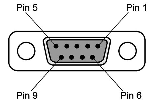
Pin Designation.
The illustration below shows the pin assignment of the DB 9 connector fitted to the instrument.
RS-232-C Interface Lines.
The Serial Interface of the instrument is connected to a start-stop synchronised serial RS-232-C circuit.
The list below names the interface lines of the 9 pin connector of the instrument.
| PIN Number | Description |
| 1 | DTR Data Terminal Ready |
| 2 | TD Transmit Data |
| 3 | RD Receive Data |
| 4 | DSR Data Set Ready DCD Data Carrier Detect |
| 5 | GND Ground |
| 6 | No connection |
| 7 | RTS Request To Send |
| 8 | CTS Clear To Send |
| 9 | No connection |
The connecting cable used to connect the instrument to the computer should be wired as given below:
| INSTRUMENT | COMPUTER |
| TD | connected to RD |
| RD | connected to TD |
| GND | connected to GND |
| RTS connected to CTS | |
| DSR connected to DCD and DTR |
Use the computer handbook to find the correct pin connections.
 |
 |
Synchronisation and Data Format.
For the instrument to communicate with the computer correctly, the instrument and the computer must be set for the same communication parameters.
Check that following parameters are set correctly
on both the computer and the instrument:
1 Start-stop synchronous system (Asynchron)
2 Start bit length
3 Stop bit length
4 Data format
5 Parity bit
6 Baud Rate
These parameters are checked and set using the Serial RS 232 Submenu in the Options menu.
See Chapter 6 for details of the Options Menu.
Hardware Handshaking.
This instrument uses both hardware and software
handshaking. The hardware handshaking uses pins
1, 7, and 8
| Pin 1 (DTR) & Pin 7 (RTS) |
There is a high signal on these pins, when the instrument is busy, e.g. during shaking and plate transport. |
While these signals are high, the instrument cannot
respond to any command from the computer.
| Pin 8 (CTS) | When there is a high signal on this pin,
the data transmission is stopped. When the signal returns to a low state, the data transmission is continued. |
Signal Levels.
The table below lists the voltage levels and their definitions.
| Voltage level | Data signals | Control signals |
| +3 to +12 | Space (Logic 0) | On |
| -3 to -12 | Mark (Logic 1) | Off |
| +3 to -3 | Undefined range | Undefined range |
Software Specifications.
The instrument is controlled by the computer and the communication between the computer and the instrument is done through the RS-232-C interface.
The communication is done using either a self written or the communications software program.
The transmitted measured data should be saved to a data disk so that it can be analysed later, using a suitable software program.
Handshake.
This instrument has a Software Handshake.
The instrument stops transmitting the data, when it receives the 'Xoff' control code (ASCII Code 19).
The instrument then waits for the computer to send the 'Xon' control code (ASCII Code 17) to start transmitting the data again.
Timing Of Messages.
While the microplate is being measured by the photo diodes, there are time spans of a maximum length of about 0.2 seconds, during which the instrument is not able to respond to any command from the computer.
While the instrument is completing the measurements, the repetition time of the status requests should not exceed every 250 ms.
This is to allow the instrument enough non-interrupted time to complete the measurement.
Communication Messages.
The communication between the instrument and the computer is done using ASCII code messages.
The messages must start with the code: Start of text = 'stx' = (ASCII code 02).
The key character which identifies the type of command must follow immediately after the 'stx' message.
The message must end with the code: Carriage return = 'cr' = (ASCII code 13).
Please note to make the commands more clear in this description, the command messages are spaced out.
If a space is required in the command message, it is indicated in this description by the use of the '_' character. Space = '_' = (ASCII code 32).
Example, 'stx ! cr' should be entered as 'stx!cr'.
Normal Mode Commands.
| Description | Commands |
| Start Remote Control | "!" |
| Status Request | "?" |
| End of remote control session | "E" |
| Choice of measurement filters xxx = measurement filter value yyy = reference filter value |
Single wavelength "F xxx" Dual wavelength "F xxx_yyy" |
| Values for the Filters fitted in the filter carriage request | "I" |
| In SPECTRA mode filter values for selected filter carriage N = carriage letter | "I_N" |
| Start normal measurement cycle | "S" |
| Display Software version number | "V" |
| Cancel measurement or error condition | "H" |
| Measurement data request | "D" |
| Dual wavelength data request (Meas., Ref.) | "D2" |
| Shake Microplate before measurement s = shaking time (1 - 250 sec) m = shaking mode and position 1 high shaking inside instrument 2 normal shaking inside instrument 3 low shaking inside instrument 4 wide shaking inside instrument 5 high shaking outside instrument 6 normal shaking outside instrument 7 low shaking outside instrument 8 wide shaking outside instrument In ATC mode the command is only remembered for 3-4 seconds, after this time the shaking is not performed |
"Y_s_m" |
| Move plate support out of the instrument, 'XXX' stands for the time in seconds the motor should be kept under voltage after reaching the outer position (000 - 300 seconds) |
"TR_1_XXX" |
| Move plate support in to instrument | "TR_0" |
| Request information, if plate support in front position | "TH" |